


ASCE 7-16 and Rooftop Wind Uplift, Part 1: What Changed, Why It Matters, and How to Read the Calculation
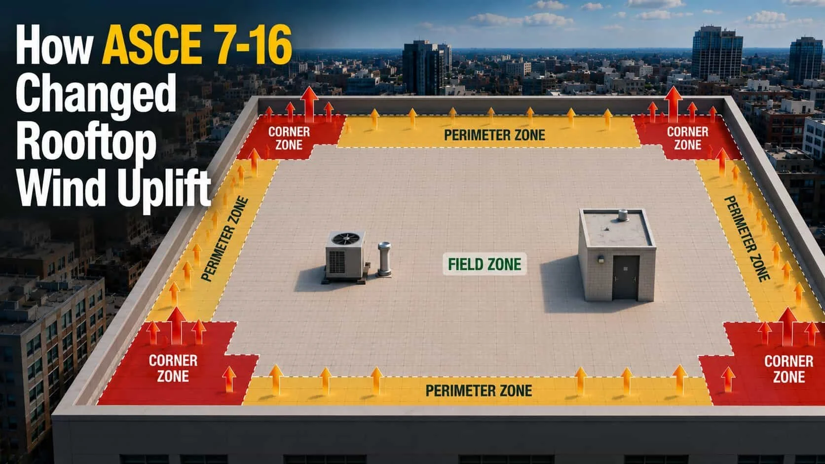
Table of Contents Show
This is the first in a series of posts Urbanstrong is publishing on ASCE 7-16 and rooftop wind uplift compliance for pedestal paver decks and terraces. Part 2 will cover restraint system selection, the engineering approval workflow, and design coordination best practices: ASCE 7-16 Rooftop Wind Uplift, Part 2: Compliance, Systems, Coordination, and Best Practices. (Link Coming Soon)
Rooftop design has evolved rapidly over the past decade. Rooftop terraces, amenity decks, podium landscapes, and pedestrian roof paver systems are now standard features on many commercial and multifamily projects, as are green roofs and mixed-use rooftop assemblies. At the same time, wind design standards have quietly shifted in ways that significantly affect how these rooftop systems must be evaluated and approved.
ASCE 7-16 introduced meaningful updates to wind uplift modeling that change how rooftop pressures are calculated, how roof zones are defined, and how uplift resistance is evaluated. While these changes have technically been in place since the 2018 International Building Code adopted ASCE 7-16 by reference, many project teams are only encountering their full implications now during design review, permitting, and construction. The standard itself is publicly available, but understanding what it means for a specific rooftop assembly and where it creates compliance exposure is where most teams get stuck.
This post covers what changed in ASCE 7-16, why it matters for rooftop paver decks, terraces, and amenity decks (and for green roofs as well), and how the wind uplift calculation actually works. For a deeper look at how to choose between restraint strategies, when mechanical restraint is required, and how to coordinate compliance across your project team, stay tuned for part two: ASCE 7-16 Rooftop Wind Uplift, Part 2: Compliance, Systems, Coordination, and Best Practices. (Link Coming Soon)

What changed in ASCE 7-16 and why rooftop designers are paying attention now
ASCE 7-16 has significantly transformed the way wind uplift is evaluated on rooftops, influencing design, safety, and compliance decisions. Architects, engineers, and designers must now consider updated pressure coefficients, expanded roof zones, and ultimate strength design requirements. These changes are particularly critical for pedestal paver decks, rooftop terraces, and amenity spaces designed for high wind conditions, where previous assumptions about weight and stability may no longer suffice, and they apply equally to green roofs and vegetated assemblies. Many design teams are only noticing the practical effects during permitting and construction because older standards or internal guidelines have persisted for years. Understanding these shifts early in the design process can prevent costly redesigns, maintain aesthetic intent, and ensure compliance with current codes.
“The code's reach is wider than most design teams realize.”
One of the less-discussed aspects of ASCE 7-16 is how far inland its wind zone coverage now extends. Earlier versions placed the high-wind hurricane zone roughly along the eastern seaboard. Under the current standard, that zone now reaches as far inland as Cleveland. Cities like Madison, Wisconsin sit outside the hurricane zone but still fall under expanded pressure requirements that are triggering mechanical restraint requirements on buildings over four stories. The code's reach is wider than most design teams realize.

Wind uplift design is no longer just a coastal concern. Projects in cities such as Cleveland and Madison may require mechanical restraint strategies that were once associated primarily with hurricane-prone regions.
How ASCE 7-16 updated wind pressure modeling and roof zone geometry
Three changes introduced in ASCE 7-16 have the biggest impact on rooftop systems:
First, wind pressure coefficients increased across most roof zones. Historically, field, perimeter, and corner zones were assigned lower pressure multipliers. Under ASCE 7-16, these coefficients increased substantially, particularly in non-interior zones. For many rooftops, this results in higher calculated uplift pressures even when basic wind speeds appear similar to prior editions.
Second, roof zone geometry was revised. Rather than using a fixed dimension for perimeter and corner zones, ASCE 7-16 defines zone depth as a function of building height. For buildings up to 60 feet tall, perimeter zones extend inward a distance equal to 0.6 times the building height. Corners are now L-shaped rather than square. For taller buildings, different geometries apply. This change means that perimeter and corner zones often extend much farther into the roof area than designers expect and on podium buildings or narrower footprints, the field zone can effectively disappear, meaning the entire roof deck falls into high-load territory.
Third, ASCE 7-16 shifted more decisively toward ultimate strength design. While allowable stress design is still permitted in some cases under the IBC, the underlying wind maps and load derivations are now based on ultimate strength principles. This shift complicates how safety factors, test ratings, and system approvals are interpreted for rooftop assemblies.
Why many teams are only encountering these issues recently
If ASCE 7-16 has been referenced in the 2018 IBC, why are so many design teams only running into it now in 2025 and 2026? The answer comes down to how building codes actually move through the system.
ASCE 7-16 is a standard published by a professional engineering society. It has no legal force on its own. It only becomes enforceable when a jurisdiction adopts a building code that references it, typically the International Building Code. The 2018 IBC was the first edition to reference ASCE 7-16, but states and municipalities adopt new IBC editions on their own schedules, often running several years behind the publication date. Some jurisdictions were still enforcing the 2015 or 2012 IBC well into the early 2020s.
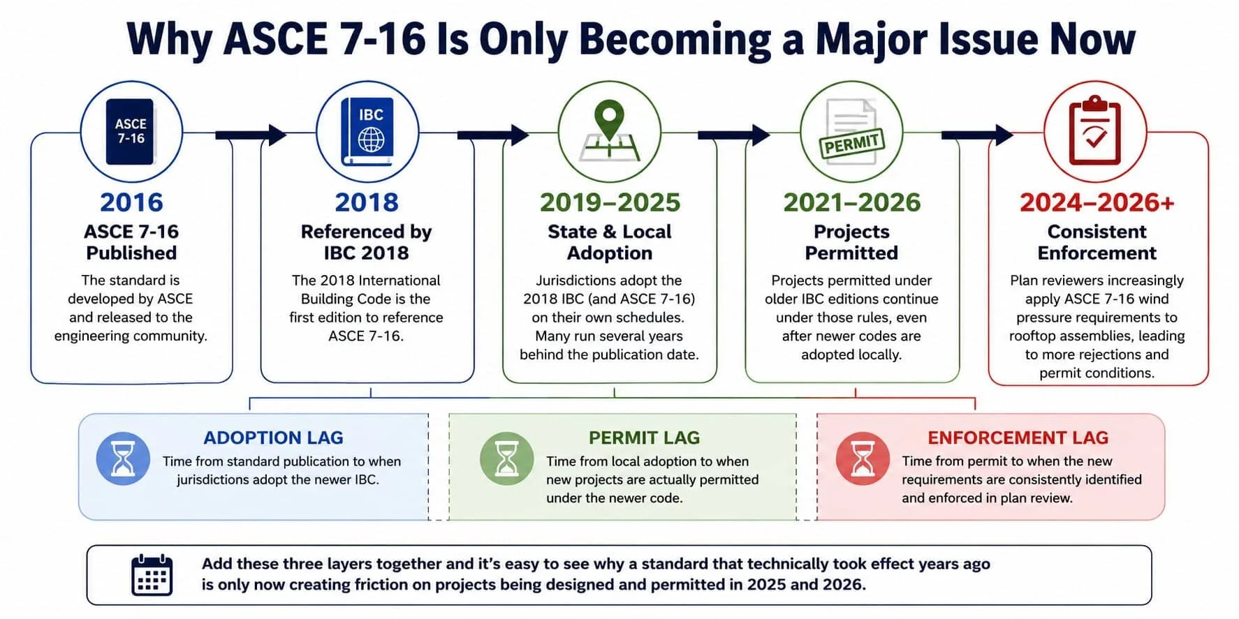
ASCE 7-16 was published in 2016, but adoption, permitting, and enforcement delays mean many design teams are only now encountering its rooftop wind uplift requirements.
Even after a jurisdiction officially adopts a newer code edition, projects that were already permitted under the previous edition continue under those older rules. A building that received its permit in 2021 under an older IBC may not be subject to ASCE 7-16 at all, regardless of when the local jurisdiction officially made the switch.
There is also an enforcement lag on top of the adoption lag. Code officials and plan reviewers do not always flag rooftop paver and green roof assemblies for wind uplift scrutiny as a matter of routine. In many markets, it took a combination of high-profile permit rejections, industry education, and updated manufacturer guidance before reviewers began consistently applying ASCE 7-16 pressure requirements to rooftop component and cladding assemblies.
Add those three layers together (publication to adoption, adoption to permit, permit to active enforcement) and it becomes clear why a standard that technically took effect years ago is only now creating friction on projects being designed and permitted in 2025 and 2026. Many design offices have also simply continued using internal guidelines or product specs that predate ASCE 7-16, without updating them as jurisdictions caught up. Awareness and early modeling are now essential for avoiding permit delays.
How wind uplift design used to work for rooftop paver decks and terraces
Weight-based assumptions and traditional ballast strategies
Historically, rooftop pedestal paver assemblies, terraces, and green roofs all relied heavily on gravity to resist wind uplift forces. Designers assumed that the mass of concrete pavers and other overburden materials provided sufficient stability. For most roof deck paver systems, this approach worked reasonably well when wind pressures were lower, perimeter zones were shallow, and interior field zones dominated. Ballast-based strategies also aligned with product testing, which emphasized the weight and distribution of the assembly rather than explicit mechanical restraint or hidden paver locking systems. While practical and cost-effective, this methodology increasingly falls short under ASCE 7-16 standards.
Why "gravity-only" solutions were historically accepted
Earlier editions of ASCE 7 calculated lower uplift pressures across roof zones, leading to less stringent scrutiny of overburdened elements like pavers and green roof layers. Plan reviewers focused on membrane and structural deck integrity, with rooftop assembly loads often implicitly assumed to meet compliance. Consequently, many rooftop systems passed permitting and review without detailed uplift analysis. These assumptions persisted until newer editions raised wind coefficients, expanded perimeter and corner zones, and emphasized ultimate strength calculations, rendering traditional gravity-only solutions insufficient in many scenarios.
What ASCE 7-16 means for rooftop wind pressures today
The combined effect of updated coefficients, revised zones, and design methodology is that rooftop uplift pressures are higher and more project-specific than before.
Increased pressure coefficients and revised roof zones
Today, rooftop wind pressures are higher and more variable due to ASCE 7-16 updates. Field, perimeter, and corner zones experience significantly greater uplift pressures than under previous editions, making perimeter and corner zones dominant in design considerations. With zone depth tied to building height, many rooftops now have minimal interior field zones, particularly on podiums or narrower buildings. Designers must account for this when planning paver layouts, vegetation placement, and rooftop amenities. Failure to do so can result in non-compliance, aesthetic compromise, or safety risks.

ASCE 7-16 wind uplift pressures vary significantly across a rooftop. Many projects can reduce cost and installation time by using mechanical restraint only in high-load corner and perimeter zones while maintaining standard pedestal systems in the field zone.
Why perimeter and corner zones are now driving design decisions
Amenity decks, landscaped terraces, and edge-focused recreational areas coincide with the highest uplift pressures, particularly in high wind conditions. These high-load zones demand careful assessment for weight, ballast distribution, and mechanical restraint. A properly designed roof wind system accounts for zone-specific pressure differences rather than applying a single solution across the entire deck. Designers who treat rooftop assemblies uniformly often encounter issues during structural review when edges are isolated for compliance calculations.
The practical upside here is real: not every area of the roof requires the same treatment. When our team worked on a pedestal paver project in Madison, Wisconsin, the structural engineering review showed that the corner and edge zones required restraint but the interior field zone did not. Designing the pedestal paver system accordingly, with concealed restraint clips in the high-load zones and standard pedestals in the field, meaningfully reduced both material cost and installation time compared to restraining the entire deck.
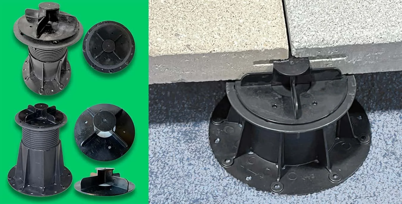
Urbanstrong’s concealed wind uplift paver pedestal assembly uses a factory kerf cut to lock rooftop pavers to the pedestal head without visible surface hardware. No time-consuming on-site cutting required.
That kind of zone-specific design is only possible when the uplift analysis happens early. The restraint system used in that project was Urbanstrong's concealed wind uplift solution for pedestal pavers, a hidden paver locking system that integrates below the paver surface with no visible or invisible hardware breaking the deck surface. Hiding the restraint system below the top level of the pavers also reduces trip hazards which can otherwise be a liability especially on amenity decks.
How this impacts rooftop paver decks, amenity terraces, and podium roofs
Weight alone is frequently insufficient for compliance near edges and corners of paver decks and terraces. Assemblies may require mechanical restraint, additional ballast redistribution, or engineered anchoring systems to meet ASCE 7-16 criteria. Green roofs face the same zone-by-zone scrutiny. Failure to address high-load zones early can result in costly redesigns, increased construction complexity, and compromised usability of amenity spaces.
Learn more about rooftop wind compliance planning
How wind uplift calculations actually work for rooftop paver systems
Understanding the calculation isn't just an engineering exercise. It's a practical planning tool that helps design teams identify where restraint is needed, how much, and why.
The 20 to 60 PSF range most projects fall into
The required uplift resistance for a rooftop paver system typically falls between 20 and 60 pounds per square foot, depending on building height, geographic location, exposure category, and roof zone. Most standard concrete pedestal paver assemblies at low-to-moderate building heights land in the 20 to 25 PSF range in interior field zones, often manageable with paver mass alone. As height increases, or as you move into edge and corner zones, that number climbs quickly. At 60 PSF, gravity-only solutions are no longer viable. That is the range where a roof tie-down system or concealed wind uplift restraint system for pedestal pavers becomes not just preferable but necessary, particularly on roof deck paver systems in high wind conditions or at significant building heights.
A hidden wind uplift solution helps comply with high wind zone region codes without impacting aesthetics or creating trip hazards.
How building height, exposure category, and occupancy affect the number
ASCE 7-16 doesn't apply a single pressure figure to all buildings. The calculation incorporates several variables: basic wind speed for the geographic location, building height, exposure category (which reflects how open or sheltered the surrounding terrain is), and occupancy/risk category. A high-occupancy residential building carries a higher risk category than, say, a mechanical equipment enclosure, and the code treats the consequence of failure accordingly. More people at risk means a higher required safety margin. This is worth understanding in early project conversations, because the same roof deck on a four-story multifamily building and a four-story data center can produce different required uplift resistance values.
A real-world example
When our team was working on a high-rise project in Chicago (a roof deck on the 64th floor), we submitted the assembly specs to our structural engineering partner for wind uplift review. The 64th floor cleared compliance. The 65th floor did not under the standard assembly configuration; additional measures would have been required. The client's scope didn't include the 65th floor, so it wasn't an issue, but it illustrates how dramatically the calculation can shift with a single story of height. Getting that answer took roughly 48 to 72 hours from submission to a stamped response, a realistic planning window to build into any project schedule.
Where to go deeper on wind uplift calculations
For a detailed walkthrough of the ASCE 7-16 wind uplift calculation methodology for roof assemblies, the National Roofing Contractors Association's trade publication Professional Roofing has a solid technical overview of the uplift calculation procedures in Chapter 30. For design teams that want to run wind uplift calculations directly, there is also a free ASCE 7-16 design pressure calculator that covers both low-rise and taller buildings. When we put together a dedicated guide to wind uplift calculations for pedestal paver systems, we will link to it here.
In the meantime, if you’re ready to think through compliance for your rooftop project? Talk with our team. Or continue to part two for a closer look at restraint systems, coordination best practices, and how the engineering approval process works: ASCE 7-16 Rooftop Wind Uplift Compliance: Systems, Coordination, and Best Practices (COMING SOON).
Frequently Asked Questions
-
Wind uplift is the upward suction force that wind creates on a rooftop surface as air accelerates over the building edge. Rather than pushing pavers down, the wind effectively tries to pull them up and off the roof. On an unrestrained pedestal paver deck, this can cause pavers to shift, tip, or become airborne, creating a serious safety hazard. The faster the wind and the higher the building, the greater the uplift force, which is why high wind conditions and tall or exposed buildings require either heavier assemblies or a concealed or hidden paver locking system to keep roof deck pavers securely in place.
-
ASCE 7-16 is the 2016 edition of the Minimum Design Loads and Associated Criteria for Buildings and Other Structures, published by the American Society of Civil Engineers. It is the standard most jurisdictions now use to determine wind, seismic, snow, and other structural loads on buildings. If your project is permitted under the 2018 International Building Code or a newer edition, ASCE 7-16 wind load requirements almost certainly apply. If you are working under an older code edition, check with your local authority having jurisdiction, as many municipalities have adopted the 2018 or 2021 IBC in recent years.
-
The design team, led by the structural engineer, is responsible for determining wind loads and compliance strategies. System suppliers assist but do not replace engineering judgment.
-
Wind uplift calculations for rooftop paver decks follow the components and cladding provisions in Chapter 30 of ASCE 7-16. The key inputs are the basic wind speed for the project location, building height, exposure category (how sheltered or open the surrounding terrain is), occupancy/risk category, and which roof zone the pavers fall in (field, edge, or corner). Those variables produce a required uplift resistance in pounds per square foot. For most pedestal paver systems at low to moderate heights, that number falls between 20 and 60 PSF. A licensed structural engineer runs the formal calculation and issues stamped drawings confirming compliance.
-
No. Requirements vary depending on building height, exposure, and roof zone. Many perimeter and corner areas now require restraint, but interior zones may still be acceptable with ballast alone.
-
Yes, in lower-pressure interior zones ballast may suffice. High-load perimeter and corner zones generally require mechanical restraint to meet ASCE 7-16 requirements.
-
Green roofs are subject to the same component and cladding pressure considerations. Vegetation and growing media can contribute ballast but must be explicitly evaluated for compliance.
-
Yes. Urbanstrong's concealed wind uplift restraint system for pedestal pavers is specifically engineered for rooftop paver decks and amenity terraces in high wind conditions, providing a fully hidden paver locking mechanism that meets ASCE 7-16 mechanical restraint requirements with no visible or surface-mounted hardware. The system integrates below the paver surface using factory-kerfed pavers and concealed restraint clips, making it invisible at the deck level while delivering the uplift resistance required in perimeter, edge, and corner zones. It works across a range of roof paver system configurations and pedestal heights up to 18 inches, and every installation is backed by stamped engineering. You can learn more or download the product data sheet for full technical specifications.
About The Author
Alan Burchell is the Principal of Urbanstrong, an award-winning firm specializing in sustainable rooftop solutions. A professional engineer, LEED-AP, Fitwel Ambassador and certified Green Roof Professional, Alan holds a degree in mechanical engineering and a Master of Science in Sustainability Management from Columbia University, with a focus on Sustainable Water Management.
For over a decade, Alan has been at the forefront of designing and implementing Solar-Integrated Green Roofs to tackle advanced rooftop stormwater management challenges. His extensive experience spans all seven continents, where he has worked as an environmentalist, project manager, speaker, and sales engineer. This global perspective enables Alan to address critical energy and water management issues, helping building owners reduce costs while complying with local codes, enhance sustainability, and boost property values.
Contact Alan today at aburchell@urbanstrong.com or 215.480.2210 or book a 15min chat directly in his calendar here.

Contact Alan today at aburchell@urbanstrong.com or 215.480.2210 or book a 15min chat directly in his calendar here.